Feed-Forward 3D Reconstruction Meets a Real AV Camera Rig
TL;DR
- Feed-forward 3D reconstruction models with a camera-conditioning port (Depth Anything 3) can handle the hard parts of an autonomous-vehicle camera rig (a wide-view camera sitting next to a tele camera, and cross-view cameras with almost no overlap), if the camera parameters are fed in correctly.
- DA3 conditioned on the calibrated cameras, with its scale re-anchored by classically triangulated points over the rig’s known baselines, produces pixel-aligned dense point clouds at a scale close to LiDAR. The remaining depth-quality gap looks like a training-distribution issue: these wide f-theta views do not seem to be in the models’ training set.
- Even with feed-forward 3D reconstruction models, you still need calibrated cameras. And a ruler.
Setup
Recently, I (along with Claude Code) tested feed-forward 3D reconstruction models on an autonomous-vehicle dataset from NVIDIA (PhysicalAI-Autonomous-Vehicles). It is a perfect setup for probing these models, because it provides synchronized multi-view frames, metric-scale LiDAR points, and relatively sparse views. Seven cameras cover 360°: three 120° f-theta cameras (cross-left, front-wide, cross-right), a 30° front tele mounted 10 cm from the front-wide, two 70° rear cameras, and a 30° rear tele. I used 14 clips (one timestep each), all verified to have LiDAR.
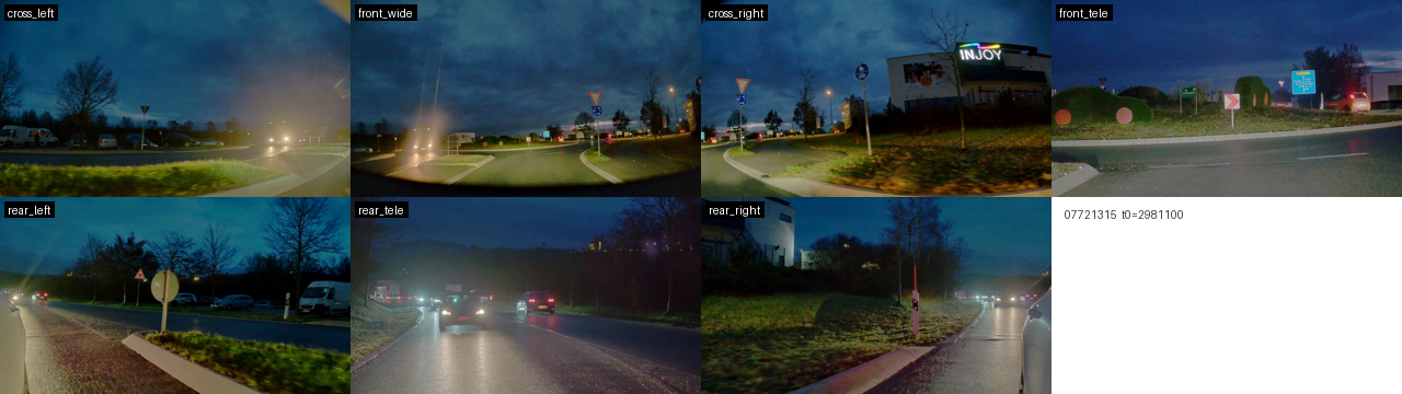
07721315.
Top: the front rig (cross_left, front_wide, cross_right, front_tele);
bottom: rear_left, rear_tele, rear_right.Prior-free models fail; the camera port fixes assembly
We first tested VGGT and VGGT-Omega; both failed to assemble the rig. DA3 without conditioning fails the same way. The stress point is the “front-wide + front-tele” pair, where the intrinsics differ by 4× while the positions are nearly identical: the models hallucinate the 10 cm baseline as a zoom-dolly of several meters. On the clip below, DA3’s own poses put the tele camera 8.5 m away from the wide camera (true: 0.10 m) and rotate the cross and rear cameras tens of degrees off calibration. I suspect the training sets of these models simply do not contain much data of this kind.
| relative rotation, front_wide → X | calibrated (°) | DA3 unconditioned (°) |
|---|---|---|
| cross_left | 67.5 | 37.8 |
| cross_right | 66.3 | 35.9 |
| front_tele | 1.1 | 7.6 |
| rear_left | 152.8 | 139.4 |
| rear_tele | 179.7 | 127.6 |
| rear_right | 152.4 | 75.8 |
However, DA3 exposes a camera-conditioning port, and we can force it to respect the input cameras. One detail matters more than it looks: the port accepts only a pinhole field of view, and the obvious pinhole fit (focal at the optical axis) announces the 121.5° f-theta lenses as 92°. Feeding the true FOV instead, and unprojecting depth along the exact f-theta rays, is what makes the rest of this post work.
| camera | true lens FOV (W×H, °) | naive axis-fit pinhole | true-FOV pinhole (used) |
|---|---|---|---|
| cross_left / front_wide / cross_right | 121.5 × 67.6 | 92.1 × 60.5 | 121.5 × 67.6 |
| rear_left / rear_right | 71.0 × 40.3 | 63.0 × 38.0 | 71.0 × 40.3 |
| front_tele / rear_tele | 29.6 × 16.9 | 29.0 × 16.6 | 29.6 × 16.9 |
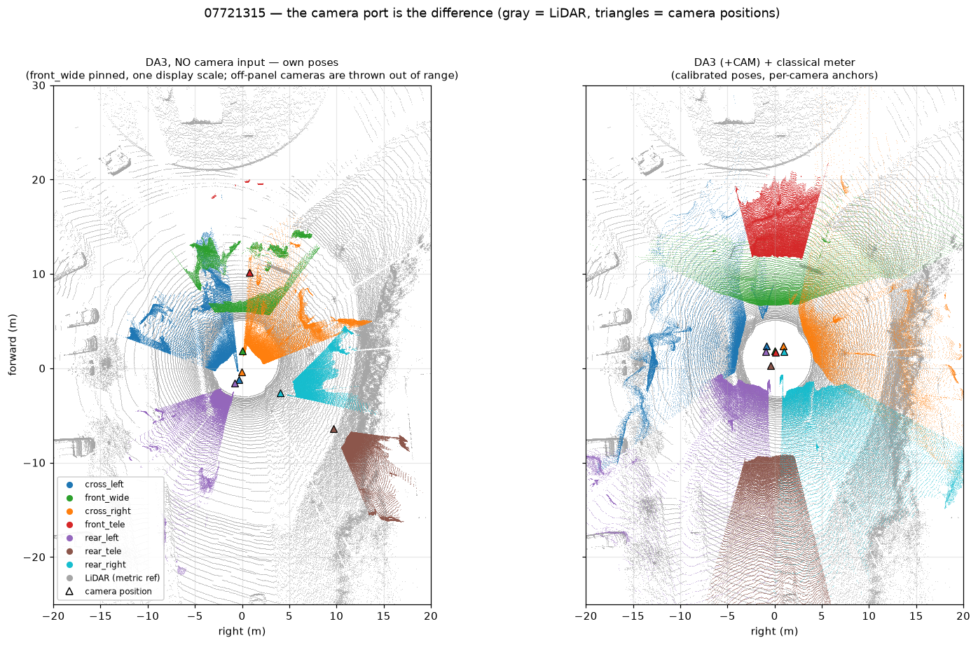
07721315, same frames as Figure 1; LiDAR (gray) is overlaid for
comparison only.Scale: the one thing conditioning does not fix
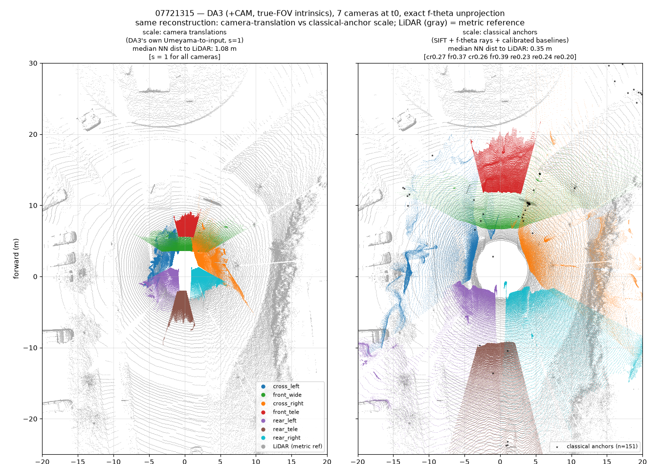
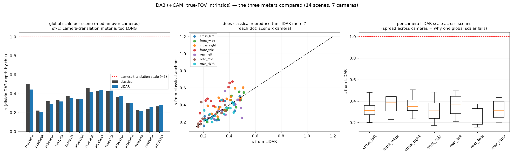
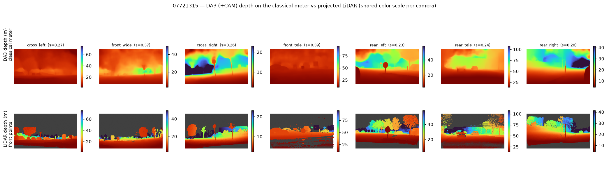
Are these pointmaps accurate enough? DA3’s output is scaled by matching its predicted camera translations to the input ones (a single Umeyama scalar), but a seven-camera constellation spanning ~2 m is a poor ruler for a 5–80 m scene: the resulting depth comes out 2–5× too short. The dataset gives us a better ruler for free: the calibrated rig distances. SIFT matches on the overlapping camera pairs, converted to exact f-theta rays and triangulated over the calibrated metric baselines (1.3–2.5 m), yield per-camera scale anchors: a classical calibration approach, no LiDAR in the loop. Aligning each camera’s pointmap with its own classical scale and overlaying LiDAR:
Gallery: the other 13 scenes
One summary per remaining clip: the input frames, the fused BEV on the classical-anchor scale, and, per camera, the input view, DA3’s depth on the classical meter, and the projected LiDAR. The captions are the dataset’s own driving-situation annotations; the set spans construction zones, pedestrians, a roundabout, highway merges, debris, and one night scene.
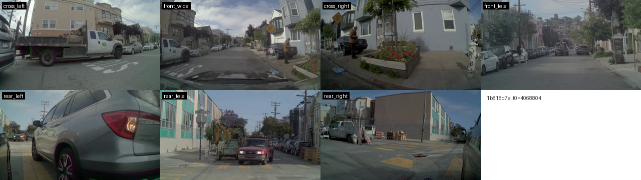
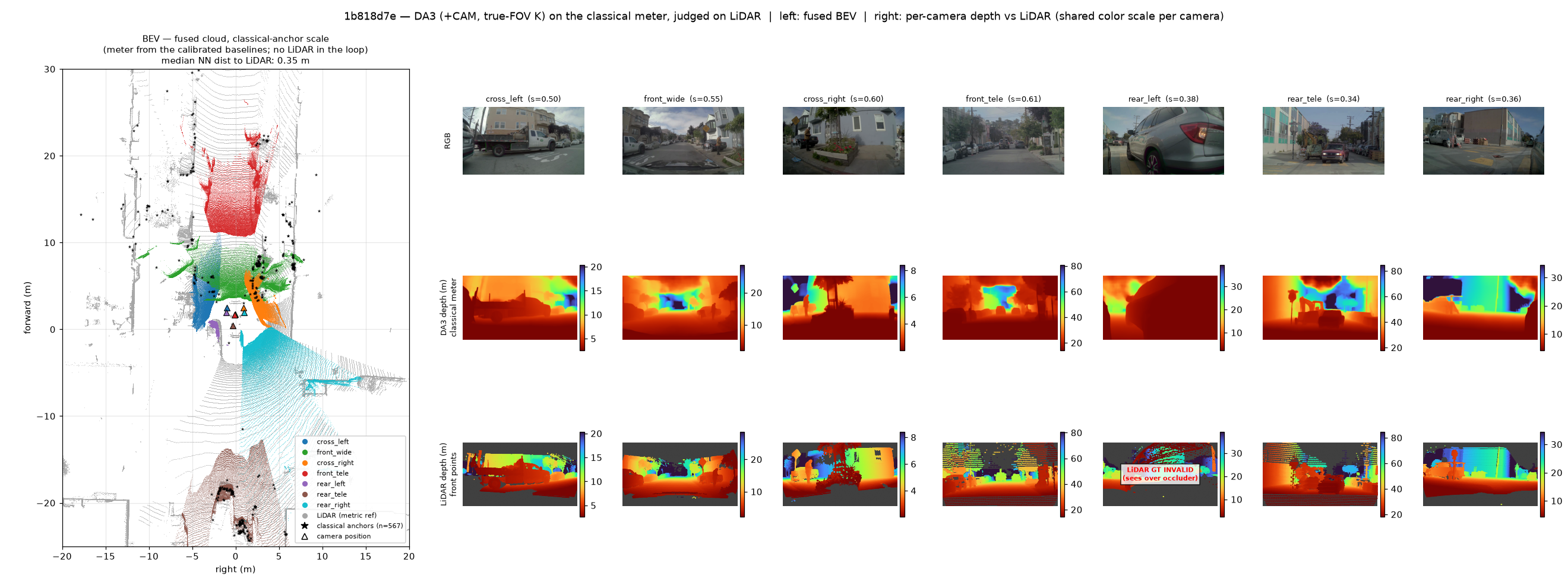
1b818d7e: Decelerate to yield to the pedestrian with a dog wanting to cross the road ahead (pedestrian density or close proximity).
Top: the 7 input frames at t0 (front rig above, rear below). Bottom: the fused
BEV on the classical-anchor scale (left, LiDAR gray) and, per camera, RGB /
DA3 depth on the classical meter / projected LiDAR (right, shared color scale
per camera).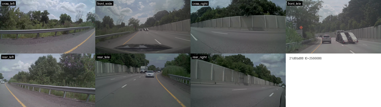
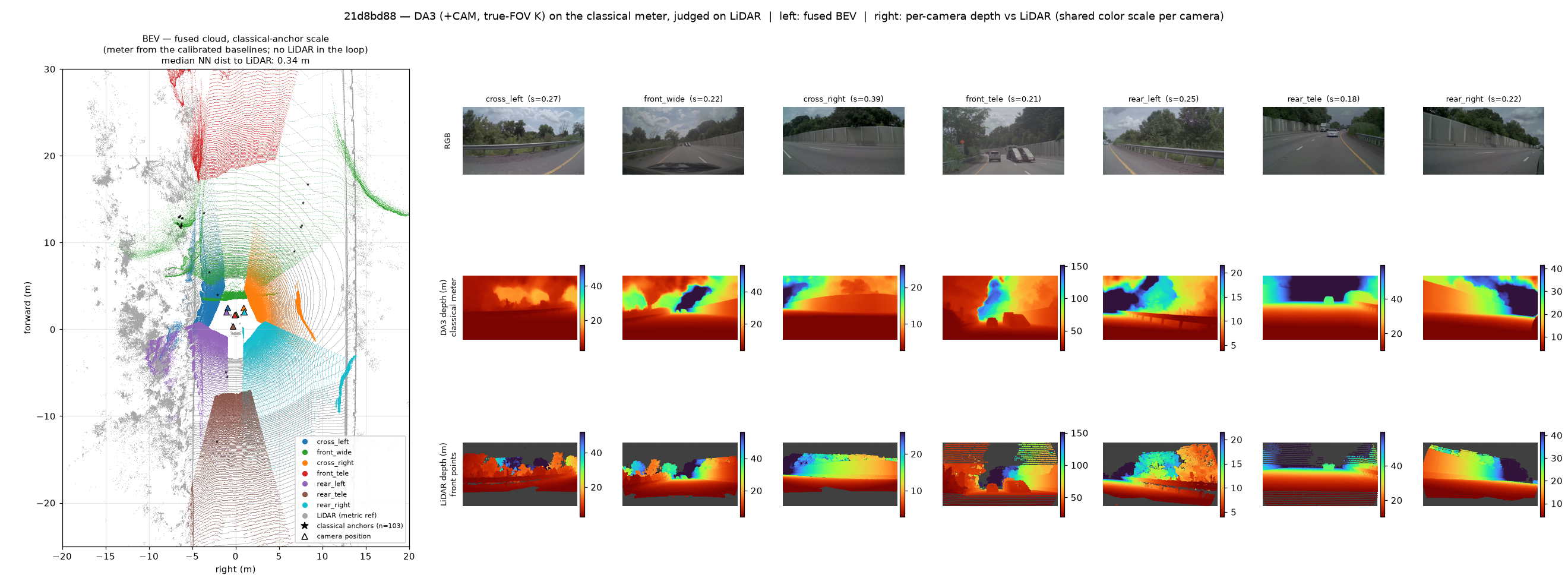
21d8bd88: Decelerate for the upcoming road curvature while keeping a safe distance from the car hauler in the adjacent lane (special or uncommon vehicle behavior).
Top: the 7 input frames at t0 (front rig above, rear below). Bottom: the fused
BEV on the classical-anchor scale (left, LiDAR gray) and, per camera, RGB /
DA3 depth on the classical meter / projected LiDAR (right, shared color scale
per camera).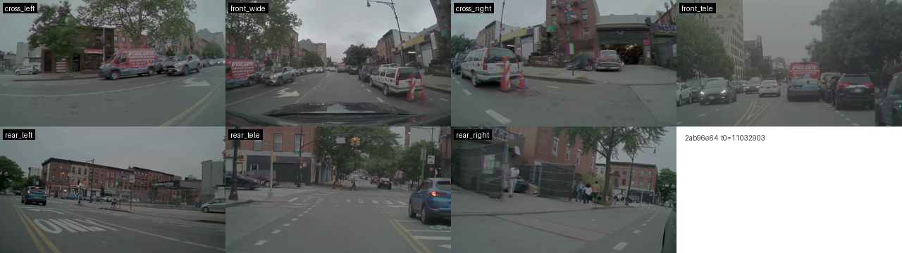
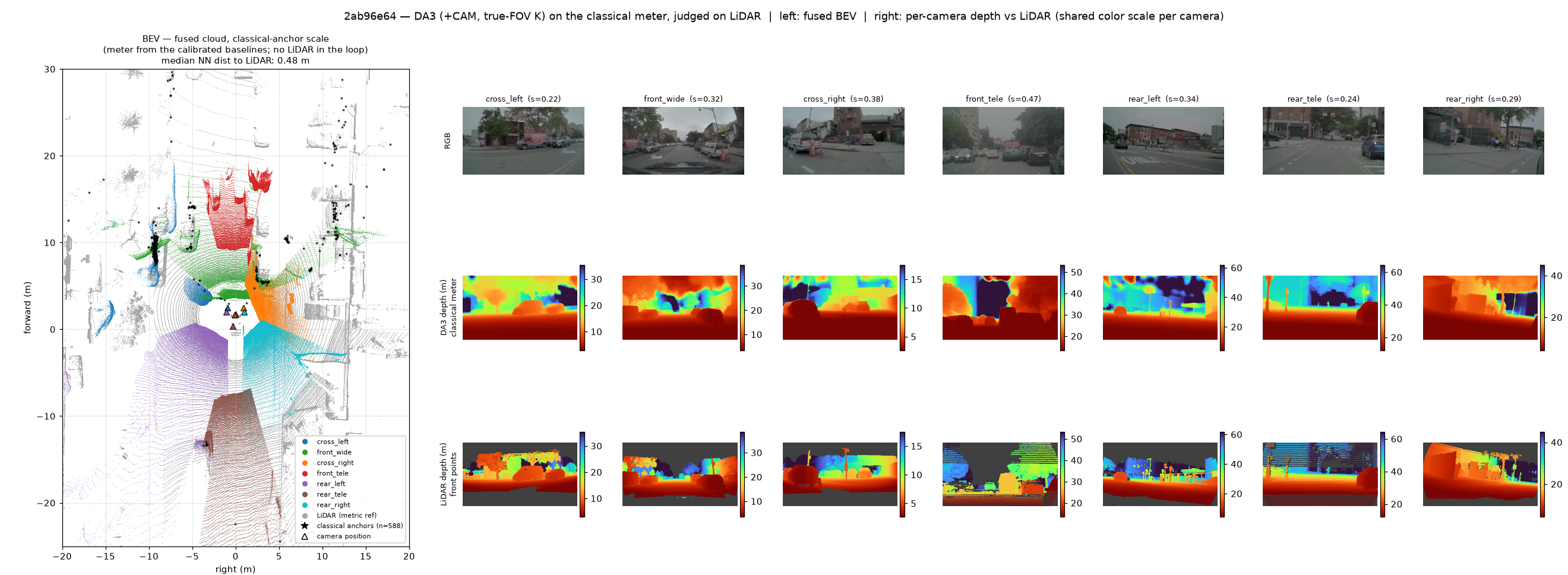
2ab96e64: Stop behind the lead vehicle in the same lane (special or uncommon vehicle behavior).
Top: the 7 input frames at t0 (front rig above, rear below). Bottom: the fused
BEV on the classical-anchor scale (left, LiDAR gray) and, per camera, RGB /
DA3 depth on the classical meter / projected LiDAR (right, shared color scale
per camera).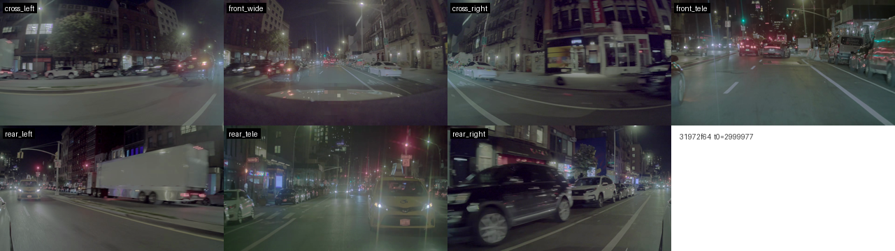
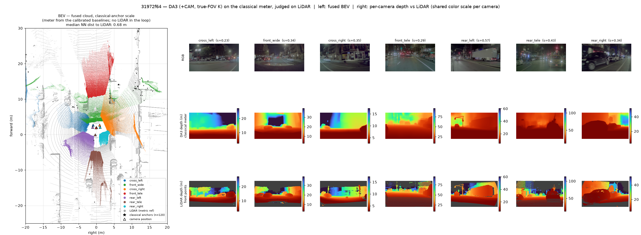
31972f64: Decelerate to yield to the merging vehicle from the left lane (special or uncommon vehicle behavior).
Top: the 7 input frames at t0 (front rig above, rear below). Bottom: the fused
BEV on the classical-anchor scale (left, LiDAR gray) and, per camera, RGB /
DA3 depth on the classical meter / projected LiDAR (right, shared color scale
per camera).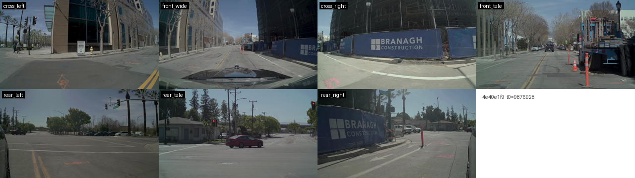
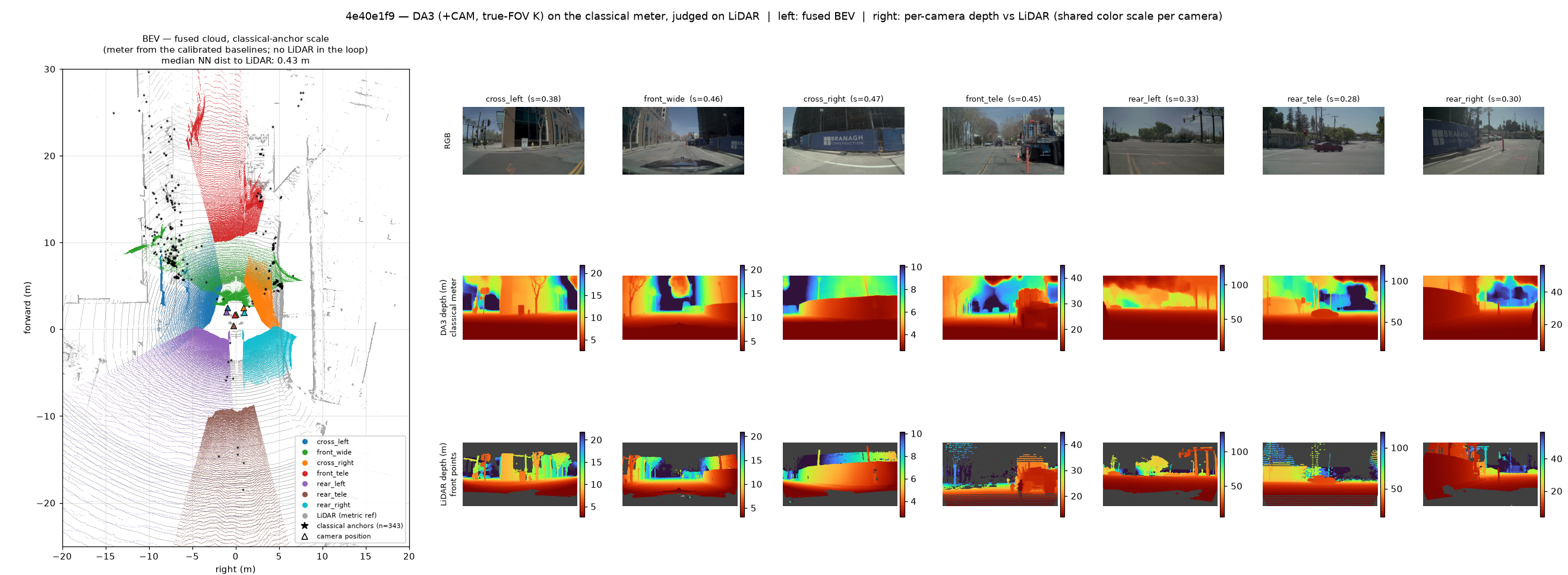
4e40e1f9: Slightly shift left to maintain a safe distance from the pedestrian crossing the road ahead (work zones temp traffic control).
Top: the 7 input frames at t0 (front rig above, rear below). Bottom: the fused
BEV on the classical-anchor scale (left, LiDAR gray) and, per camera, RGB /
DA3 depth on the classical meter / projected LiDAR (right, shared color scale
per camera).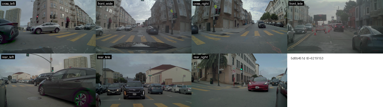
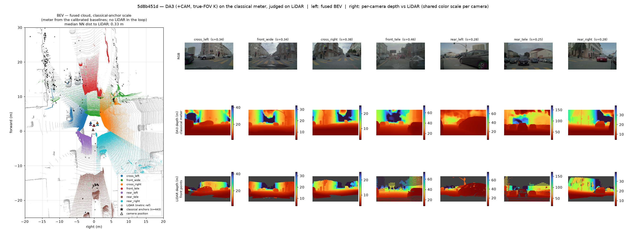
5d8b451d: Steer right to keep a safe distance from the construction zone with traffic cones in the same lane (work zones temp traffic control).
Top: the 7 input frames at t0 (front rig above, rear below). Bottom: the fused
BEV on the classical-anchor scale (left, LiDAR gray) and, per camera, RGB /
DA3 depth on the classical meter / projected LiDAR (right, shared color scale
per camera).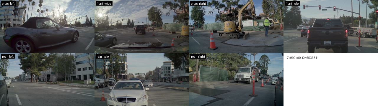
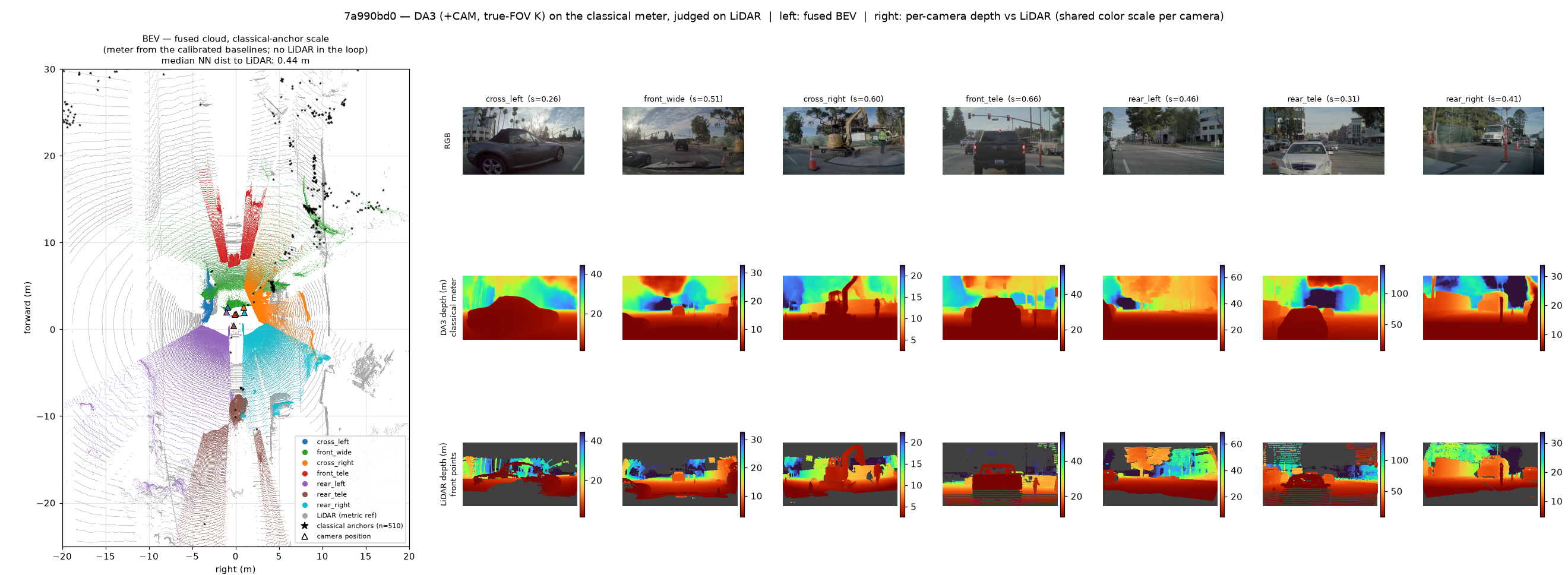
7a990bd0: Maintain speed while following the lead vehicle and navigating through the construction zone with traffic cones (work zones temp traffic control).
Top: the 7 input frames at t0 (front rig above, rear below). Bottom: the fused
BEV on the classical-anchor scale (left, LiDAR gray) and, per camera, RGB /
DA3 depth on the classical meter / projected LiDAR (right, shared color scale
per camera).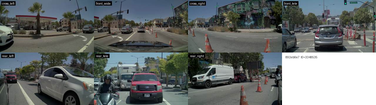
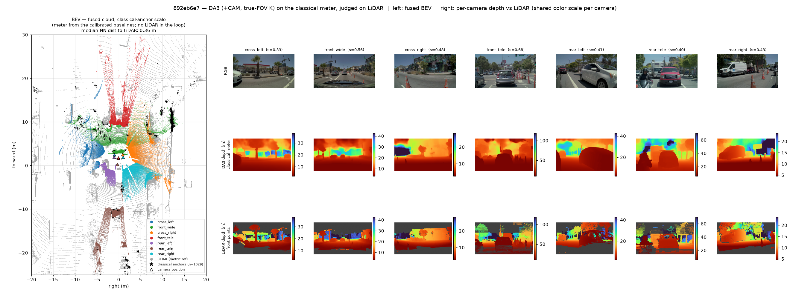
892eb6e7: Steer left to keep a safe distance from the construction zone ahead (work zones temp traffic control).
Top: the 7 input frames at t0 (front rig above, rear below). Bottom: the fused
BEV on the classical-anchor scale (left, LiDAR gray) and, per camera, RGB /
DA3 depth on the classical meter / projected LiDAR (right, shared color scale
per camera).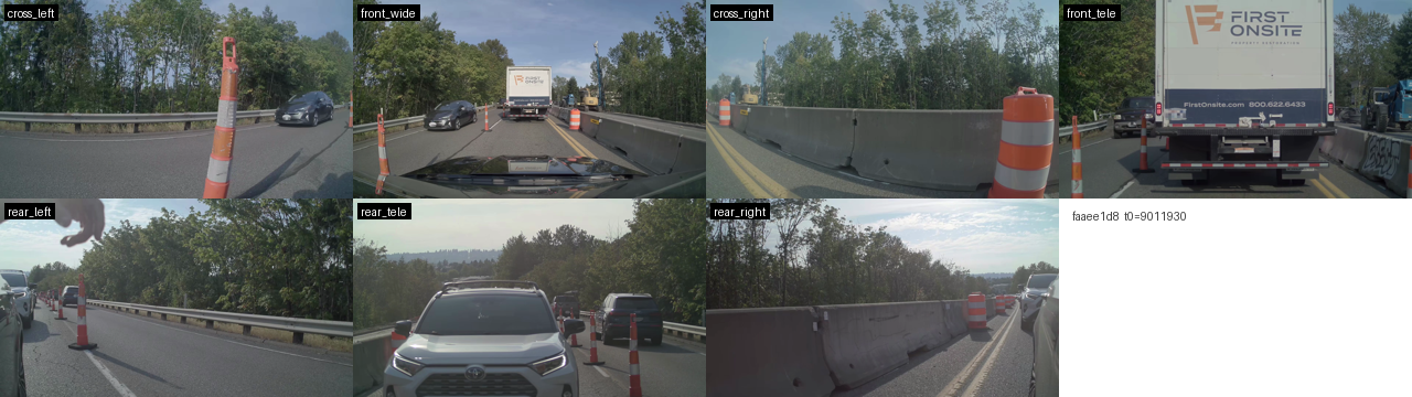
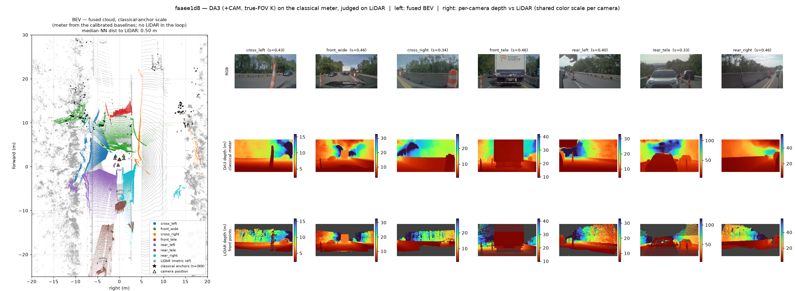
faaee1d8: Go straight following temporary traffic cones while keeping a safe distance from the lead vehicle (work zones temp traffic control).
Top: the 7 input frames at t0 (front rig above, rear below). Bottom: the fused
BEV on the classical-anchor scale (left, LiDAR gray) and, per camera, RGB /
DA3 depth on the classical meter / projected LiDAR (right, shared color scale
per camera).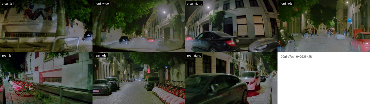
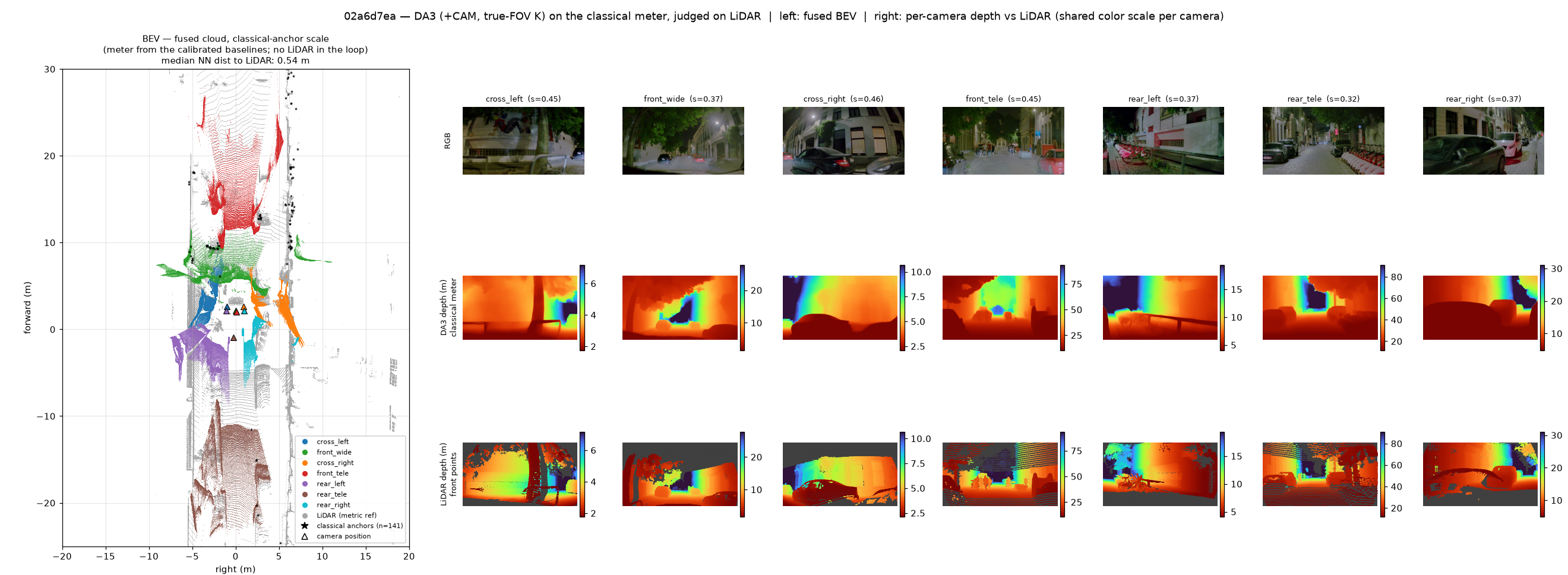
02a6d7ea: Gentle deceleration to maintain a safe distance from the pedestrians and cyclists ahead (cyclists and micromobility complex).
Top: the 7 input frames at t0 (front rig above, rear below). Bottom: the fused
BEV on the classical-anchor scale (left, LiDAR gray) and, per camera, RGB /
DA3 depth on the classical meter / projected LiDAR (right, shared color scale
per camera).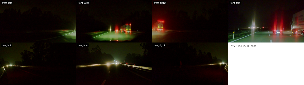
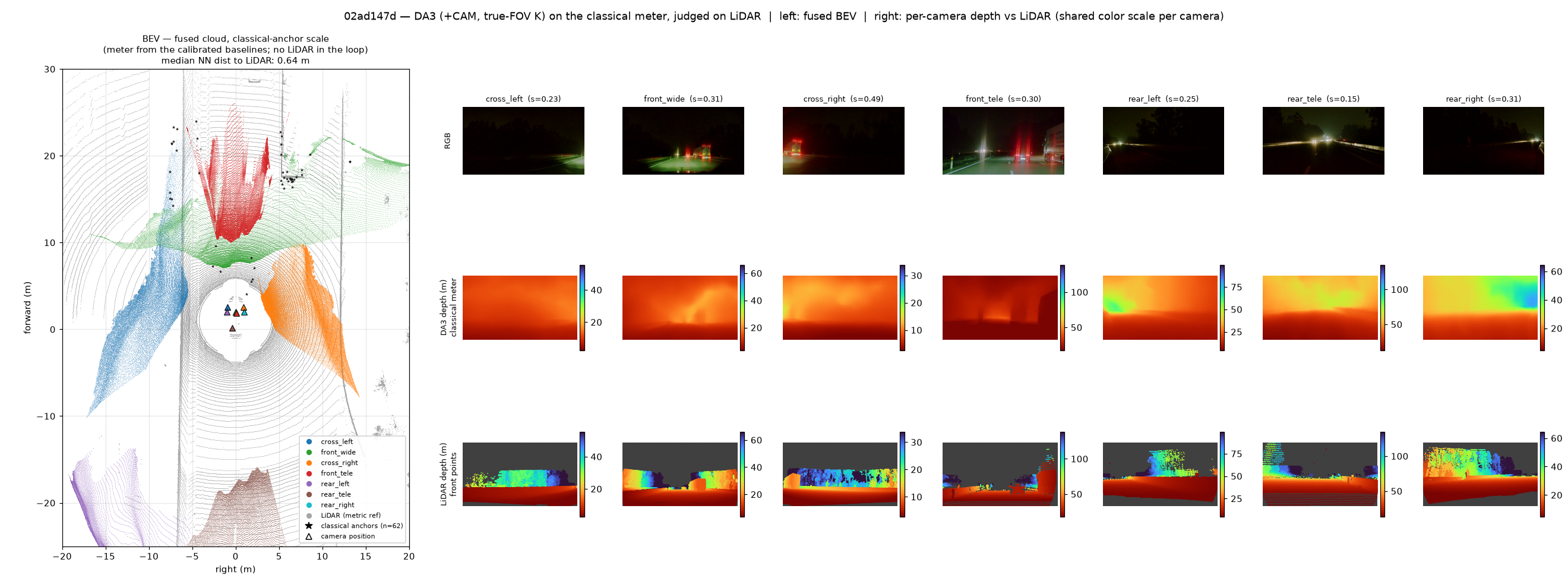
02ad147d: Gentle deceleration after passing the lead vehicle on the left (other longtail).
Top: the 7 input frames at t0 (front rig above, rear below). Bottom: the fused
BEV on the classical-anchor scale (left, LiDAR gray) and, per camera, RGB /
DA3 depth on the classical meter / projected LiDAR (right, shared color scale
per camera).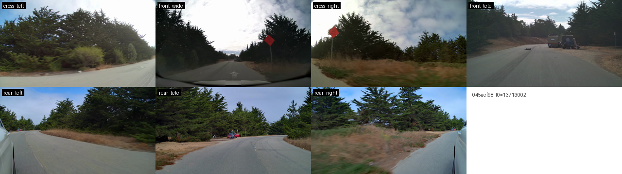
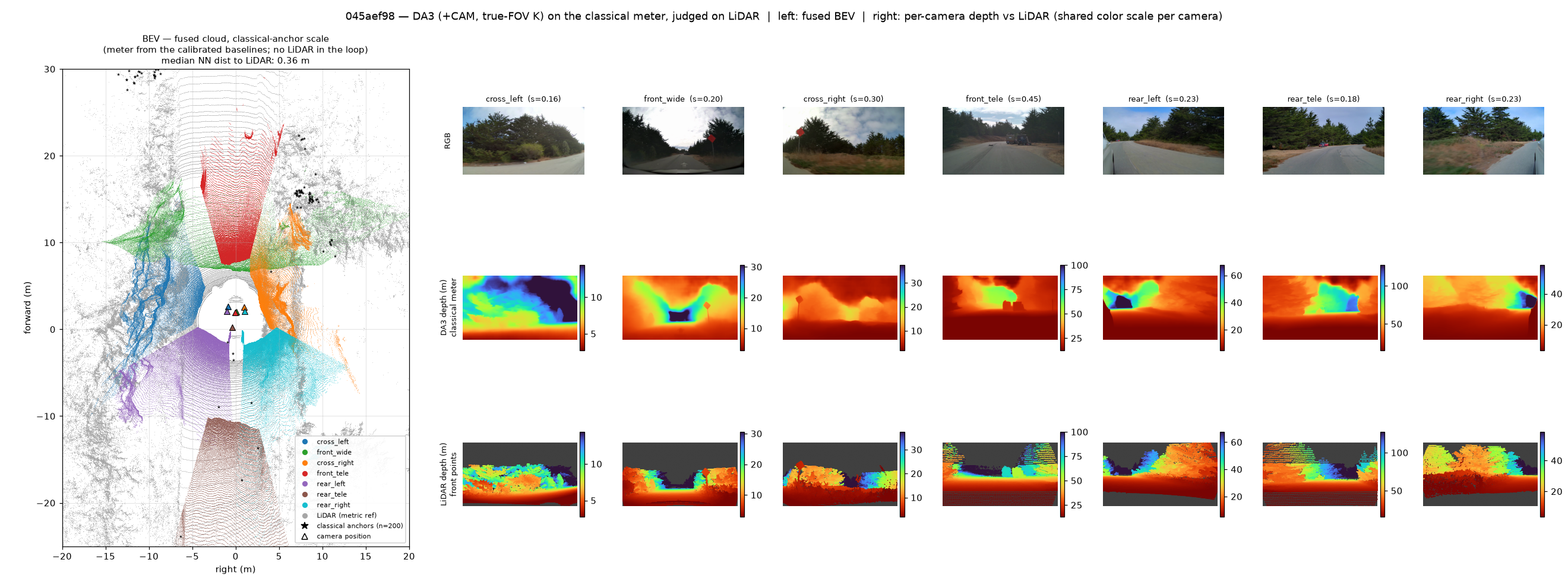
045aef98: Decelerate for an obstacle in the road (road debris or safety traces).
Top: the 7 input frames at t0 (front rig above, rear below). Bottom: the fused
BEV on the classical-anchor scale (left, LiDAR gray) and, per camera, RGB /
DA3 depth on the classical meter / projected LiDAR (right, shared color scale
per camera).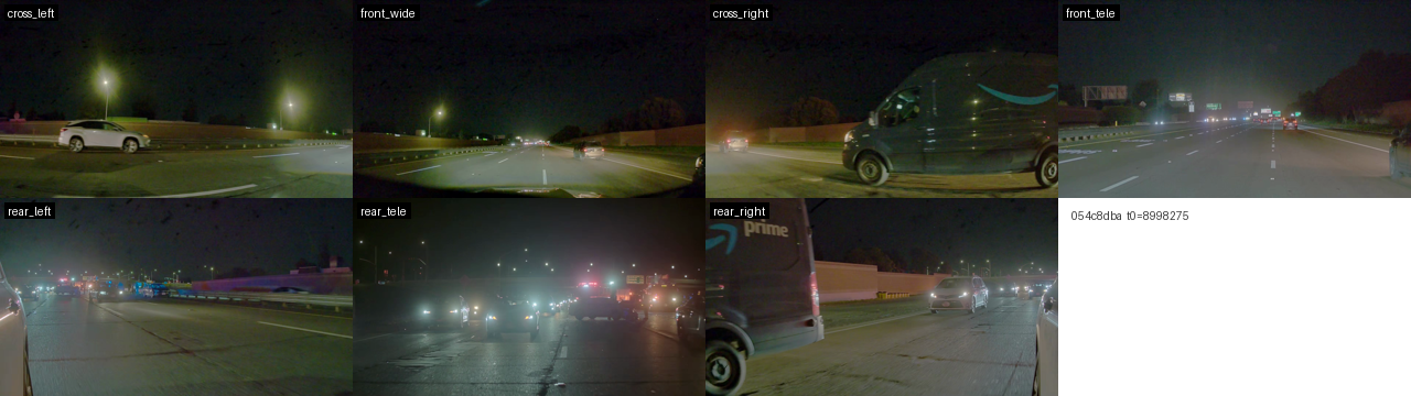
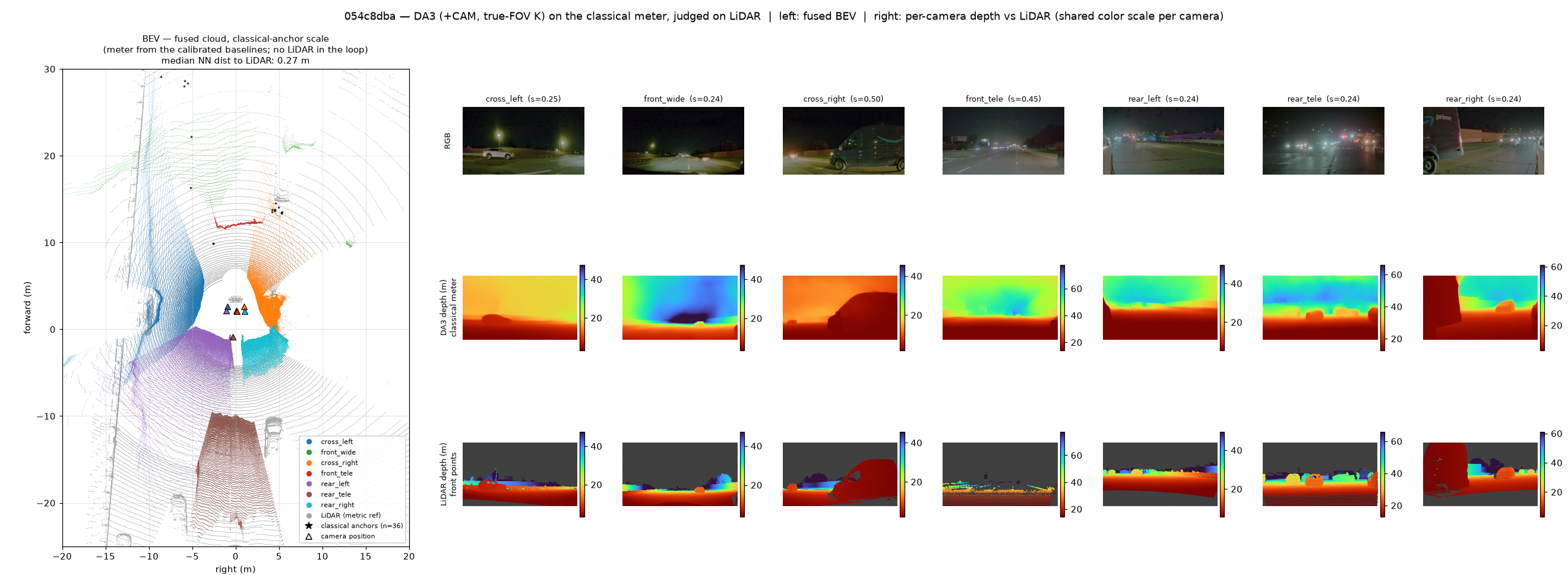
054c8dba: Pass/Overtake while maintaining a safe distance from the lead vehicle ahead (emergency incident scene).
Top: the 7 input frames at t0 (front rig above, rear below). Bottom: the fused
BEV on the classical-anchor scale (left, LiDAR gray) and, per camera, RGB /
DA3 depth on the classical meter / projected LiDAR (right, shared color scale
per camera).Quantitative comparison, all cameras
We can also compare quantitatively against LiDAR, using only valid LiDAR points (projected through the exact f-theta model, occlusion-tested, 1–80 m). The table scores DA3 (+camera) depth divided by its per-camera classical scale; numbers are medians over the scene×camera cells of all 14 clips. bias is the median predicted/LiDAR depth ratio (0.96 means the classical meter is essentially unbiased), and AbsRel is the mean relative depth error.
| camera | AbsRel | δ<1.25 | RMSE (m) | bias | AbsRel <25 m | AbsRel ≥25 m |
|---|---|---|---|---|---|---|
| cross_left | 0.323 | 0.426 | 6.53 | 1.02 | 0.283 | 0.463 |
| front_wide | 0.257 | 0.596 | 5.68 | 1.04 | 0.272 | 0.285 |
| cross_right | 0.322 | 0.449 | 3.76 | 0.85 | 0.271 | 0.296 |
| front_tele | 0.319 | 0.160 | 12.13 | 0.68 | 0.267 | 0.436 |
| rear_left | 0.240 | 0.568 | 9.11 | 1.01 | 0.220 | 0.270 |
| rear_tele | 0.175 | 0.766 | 8.26 | 0.94 | 0.136 | 0.162 |
| rear_right | 0.266 | 0.692 | 6.22 | 1.03 | 0.298 | 0.191 |
| all cells (median) | 0.264 | 0.552 | 7.89 | 0.96 | 0.256 | 0.273 |
To be frank, an AbsRel of 0.26 is not deployment-grade depth: fine-tuned in-domain monocular models reach 0.05–0.09. But the meter is right (bias ≈ 1.0 from a LiDAR-free pipeline), and the error concentrates exactly where the training distribution ends: the periphery of the 120° lenses runs about 2× worse than their centers, and the best camera is the most pinhole-like one (rear tele). That reads as a fine-tuning gap, not a method failure.
Closing
This is the end of my weekend experiments on a multi-view AV dataset. 3D reconstruction models paired with proper camera parameters and classically calibrated points can generate dense, metric pointmaps, and they seem to address nearby large objects better than a sparse LiDAR spin does. It once again shows the importance of getting the camera parameters right in multi-view settings (even for learning-based 3D reconstruction models), and of knowing where your scale actually comes from. Originally I wanted to try time-lapse 3D reconstruction, but already at t = 0 the model failed to reconstruct the scene without camera conditioning, so I focused on reconstructing 3D pointmaps properly from RGB images and their viewpoints.
This experiment also reminds me of the prism goggle experiment. Prisms shift everything, say, 15° to the right. When you first reach for an object, you miss to the right. Within dozens of reaches, you recalibrate and reach accurately. Crucially, when you remove the goggles you miss in the opposite direction, the negative aftereffect, which shows genuine remapping of the visuomotor transform rather than conscious correction. Perception is a learned, plastic sensor-to-action mapping rather than a fixed geometric pipeline: the brain treats the shifted input as a calibration problem and re-solves the transform online, driven by prediction error from active interaction. We understand the world with our two eyes, but we constantly calibrate our perception with our actions. 3D reconstruction models with camera conditioning are like the visual system behind the goggles: they can learn to reconstruct 3D from RGB images, but they need to know where their viewpoints are, and that calibration comes from classical methods and a ruler.
If you have any feedback, corrections, or ideas for follow-ups, I would love to hear them: send me an email.
Code & notebook: github.com/wbjang/av-rig-da3-demo. Models: Depth Anything 3, VGGT, VGGT-Omega. Data: NVIDIA PhysicalAI-AV (gated).